
Project Diary: For Reference Only
The power of a strawman/reference design in planning projects

“ [A drawings] is a line around my thoughts” —Gustav Klimt
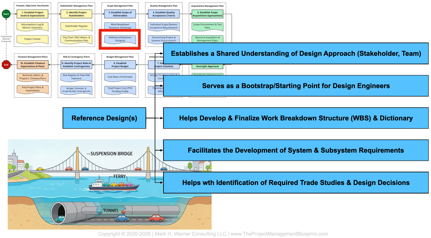
Imagine you’ve been assigned as the project manager for a new transportation link across a wide river. Everyone agrees on the goal: enable vehicles to cross the water efficiently, safely, and year‑round. In your mind, that obviously means a bridge, so you kick off conceptual design assuming a mid‑span suspension structure with generous clearance for ship traffic. About halfway through, as scope, cost, schedule, and risk numbers solidify, a key stakeholder casually mentions how excited they are about finally getting a tunnel under the river; another chimes in that they had always assumed you would buy a small fleet of roll‑on/roll‑off ferries; and a third says a bridge is what they thought, too, but they were picturing a straightforward truss bridge, not the grandiose signature suspension span your engineers are quietly optimizing. By this point, analyses have been run, procurement paths are being scoped, and expectations are diverging instead of converging...
…okay, this is an extreme example, but you should still get the point: confusion could have been surfaced and resolved early if, back at the beginning, you had forced yourself and your stakeholders to react to a simple reference design: a rough sketch that made it explicit whether “cross the river” meant a tunnel, a ferry system, a truss bridge, or a suspension bridge—and what that choice implied for scope, interfaces, and trade‑offs.
TL;DR
What: A reference design is a simple, provisional system‑level sketch that shows what the major pieces of a project are, and how they fit together. Also known as a “strawman” design, a reference design is a core tool in Step 3 of the PM Blueprint: defining and documenting scope.
Why: Building a strawman reference design early exposes gaps in scope and requirements, highlights key trade‑offs, and gives everyone—from engineers to stakeholders—a shared mental model of the system.
How: Block off focused time with the right people, sketch an intentionally rough “cartoon” of the system, and then use that sketch to drive scope discussions, requirements gathering, interfaces, trade studies, onboarding, and stakeholder conversations.
What: Reference Designs in the PMB
A fundamental aspect of the Project Management Blueprint is defining and documenting the scope. For project managers, that ultimately means creating a work breakdown structure (WBS) and accompanying dictionary. It means making clear what is in and out of the project, what major deliverables you handle, and where your boundaries and interfaces lie. But often overlooked during this process is the creation of a so-called “reference design.” That’s bad news, as a reference design is one of the more effective tools you can use to define scope. Instead of only writing scope in prose, you also draw it.
A reference design (also often called a “strawman” design), is a deliberately simple, system‑level representation of your project’s deliverables. Think of it as “cartoon architecture”: a handful of key blocks, with arrows showing how they connect, sit in space, and pass things like information, forces, or, with telescope design, light. It is not a polished CAD model or a detailed P&ID. It is a high‑level sketch that is “real enough” to ask tough questions of. In the blueprint, this sketch (or sketches) becomes the visual anchor that holds together everything from your scope statement, your requirements, and your work breakdown structure, to the management of stakeholder expectations.
Equally important is what a reference design is not. It is not the final design. It is not even a conceptual design. It is not a commitment to specific components, vendors, or details. It is not a straitjacket that forbids alternatives. Instead, it is a working hypothesis, a best current guess at how the system might hang together. Its job is to bootstrap the project, provoke better questions, expose hidden assumptions, and give the team something concrete to push against while you are still early enough to change your mind cheaply.
Why: Why Reference Designs Matter for Scope and Requirements
Work breakdown structures are a type of documented, shared understanding. A reference design makes that understanding visible. When you draw the system, block by block, you are forced to decide what belongs on the page and what does not. That immediately clarifies what is inside your project’s responsibility and what lives elsewhere. Missing blocks or “mystery arrows” often reveal scope gaps that would never show up in a generic scope statement.
Reference designs also improve requirements. When you look at each block and interface on the sketch, you can ask structured questions: “What does this need to do? How well does it need to do it? What can go wrong here? Who owns this interface?” Those questions eventually turn into functional, performance, interface, and environmental requirements. Because the diagram is simple and shared, subject matter experts (SMEs) from different disciplines can react to it quickly. They are no longer staring at a blank page; they are responding to a concrete proposal.
The sketch also highlights trade‑offs, required analyses, and risks. A reference design makes “forks in the road” very obvious: spots where there is design space to explore, areas where design choices have already been made, and how functional needs will be distributed. Those forks are where real trade studies belong. By making them visible early, you can plan analyses, simulations, and prototyping instead of drifting into an implicit decision by default. The diagram becomes the picture everyone points at in meetings, including scientists, engineers, managers, and sponsors. That kind of clarity is hard to get from text alone.
How: Building and Using a Reference Design on Any Project
You do not need a telescope project or a giant budget to benefit from a reference design. You can build one on almost any project if you approach it intentionally.
The first step is to create focused time and get the right people in the room. Pick a small group that understands the system end‑to‑end, even if only at a high level. Block off a few hours to a full day. Treat it like a working session, not a side conversation squeezed between emails. If you can, close the laptops, silence the phones, and clarify that the goal is to walk out with a credible strawman design—not a perfect one, just something everyone can see and critique.
The second step is to start ugly and stay system‑level. Begin by drawing the major functional or physical blocks and the main flows between them. For a software system, that might be blocks representing users, front‑end, services, databases, and external APIs. For a facility, it might include buildings, processing elements, structures, utilities, and outputs. Do not worry about alignments, fonts, or whether a block is “to scale.” Once you have a first sketch, deliberately draw one or two variants. For each variant, list the pros and cons on the board. The differences between the versions are where requirements and trade‑offs live.
The third step is to use the strawman to drive scope and requirements discussions. Go block by block and interface by interface. Ask what must be true, what is definitely not your responsibility, and where you are uncertain. Capture clear requirements, open questions, and potential trade studies. Label the diagram as “Reference Design v0.1” or similar to make its provisional nature explicit. Expect it to evolve as you learn more. Finally, put the reference design to work. Include it in onboarding materials; use it to define where new employees will work and be responsible. Walk stakeholders through it when you explain the scope. Open it back up at key milestones as a living artifact, not a one‑off sketch that disappears into a notebook.
How: A Day with ngGONG’s Opto‑Mechanical Reference Design
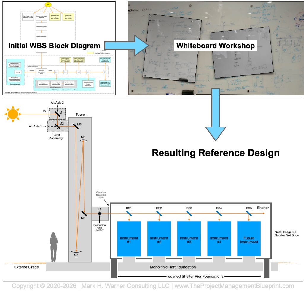
On ngGONG, we recently did exactly this for the opto‑mechanical layout. I invited a senior, very experienced engineer to join me for a focused working day. The goal was simple: walk out with a first‑cut reference design for the overall opto‑mechanical structure of the ngGONG system. A secondary goal was to create layouts of our high-level software and data management system pipelines. We booked a conference room, closed the door, and agreed up front: no email, no diversions, no “quick calls” unless the building was on fire. For that day, the reference design was the job.
We started with a really rough one-line diagram that was created back when we were developing the proposal. We coupled that with a big blank whiteboard in the conference room. The first sketch was as simple as possible: where the light comes from and enters the facility (we literally drew a cartoon of the sun with rays flowing out of it), how it travels through major optical elements, how the telescope structure holds and moves those elements, where instruments sit, and where data leaves the system. It was not pretty. Boxes were lopsided, arrows were crooked, and labels were abbreviations. That was fine. The point was to get a complete path on the board from “Sun” to “data product” with enough structure to argue and poke holes in.
From there, we iterated. We drew one variant where certain assemblies were co‑located, then another where they were separated. We argued about gravity vectors, structural envelopes, maintenance access, thermal effects, and alignment tolerances. For each option, we listed pros and cons on the board: performance, complexity, & risk. Several times we erased large sections and started again, because a constraint we had parked in the back of our minds suddenly mattered. By mid‑afternoon, we had gone through enough cycles that a particular layout felt “cleaner” than the others: fewer awkward interfaces, better consistency with the science goals, and fewer hidden traps in the mechanics. Along the way, we took periodic photos of the whiteboard to document different versions before they were erased.
By the end of the day, we had a basic opto‑mechanical reference design. It was still a cartoon, but it was a coherent cartoon that we cleaned up into a PowerPoint sketch. Both of us believed it was realistic enough to distribute to a wider audience. That sketch now does several jobs for ngGONG. It is a starting point for deriving specific requirements on things like stiffness, pointing, alignment, and environmental control. It highlights where we need trade studies—for example, which structural configurations should be compared formally, or where different optical layouts might be worth analyzing. It gives new engineers a fast, visual orientation to the system. And it provides a single picture we can use with advisory boards and sponsors when we explain where we’re headed.
On a personal level, that day was a reminder of how powerful it is to step away from the email inbox and project management reports, and just think with a dry-erase marker in your hand. The quality of the reference design had as much to do with the uninterrupted time and honest debate as it did with any particular insight. By the time we left the room, tired and with the whiteboard covered in half‑erased ghosts of earlier ideas, we had moved the project forward tangibly.
Bottom Line:
Creating a reference design is one of the most effective things you can do in Step 3 of the PM Blueprint. A simple, provisional sketch of the system forces clarity about what is in scope, what is out, and where the critical interfaces and trade‑offs lie. It keeps you from waking up halfway through “designing a bridge” only to discover that you should have been working on a tunnel. Early “cartoon architecture” can solve this issue, plus it forms a concrete basis for writing better requirements, planning trade studies between options, onboarding new team members with the project plans, and communicating with stakeholders in a shared visual language. Whether we’re sketching ngGONG’s opto‑mechanical layout, or the high‑level concept for getting vehicles across a river, the reference design is how we draw a line around our thoughts early enough that the whole team can see it, challenge it, and commit to building the same thing.